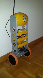
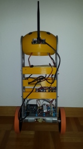
During the last 9 months I have been busy working on my latest robotic project: a two wheeled self-balancing robot. I previously wrote about the reasons; in essence I think it is a great way to better understand the technologies that surround us and also a good personal development to derive some teachings about management and leadership on which I will soon write.
In the beginning I thought it would have been a few week-ends project; now almost one year in the process I just started scratching the surface of it. I thought that I had most of the necessary knowledge, instead I had to learn new tools, new programming languages and new engineering concepts.
The purpose of this article is to outline particular aspects of the design of the robot with special regards to some tricky issues I solved long the way, not to be a step-by-step guide. In case you are interested in missing details just drop me a line and I will do my best to provide you the information.
Knowledge needed
The project is multidisciplinary and you will need to have a good grasp of many elements of engineering, software development and physics.
- Inverted pendulum physics – this is the fundamental model of the system. The robot senses the tilting angle and corrects it by applying momentum to the wheels. It is very much like balancing a broom upside down on the palm of your hands: you see the broom moving away from its equilibrium and you move your hands to compensate.
- Control theory – from the engineering perspective it is a non-linear, unstable mechanical control problem, so the control strategy is the one thing that must be mastered. I suggest to start with the Proportional Derivative Integral (PID) as it is simple to understand and implement.
- Signal acquisition and filtering – the world is a messy place and sensors rarely output stable measures that can be used to take decisions. So this part really makes a difference. Luckily there are plenty of libraries to choose from as some of the concepts like Kalman filters might me mathematically daunting.
- Electronics – you will need basic knowledge of which component to choose and how to integrate them into the system. This seems simple for a robot using a relatively limited number of components but I made every possible mistake. For example I got the wrong motor driver, the very expensive one I bought in first instance was not suited for the application and had to replace it with a simple, few dollars one that worked very well (will write about this lesson in my other article).
- Programming – I have a Raspberry Pi connected with an Arduino Mega via USB and I use a tablet to remote control the robot. This implies that you need to be able to use some advanced features (e.g.: multitasking, events, non-blocking code, etc) of at least 3 platforms. Also here I was stuck several time and had to learn new languages and re-write entire programs just because the platform I choose in first instance was not really a good fit for the application. Frustration? No! Learning opportunity!
- Design – I made the 3D printed parts from the scratch and had to learn how to use a CAD modelling system.
Construction
I think one of the highlights of my robot is that the structure is mostly 3D printed. I wanted the robot to be replicable and not having a workshop at home I decided to use my Ultimaker 3D printer to do it. This is the first project and I have to say I am impressed on how easy is to create functional shapes with a good 3D printer. I quickly learned to design in Openscad and in a few days the key aspects of the robot were ready. I like this software because is a different type of CAD. The designer cannot use the mouse to create shapes but have to write the instructions in terms of primitives or transformations in a terminal window; the rendering pane is just to verify the final result.
For example this creates a sphere:
sphere(r = 15);
And this moves the same sphere up on the z axis:
translate([0, 0, 20])sphere(r = 15);
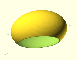
This at first might seem not intuitive but it is extremely fast and powerful if you can recall notions of descriptive geometry. It is easy for example to create two perpendicular plates or to define parametric designs. When the model is ready you just have to process it via Cura, save it on the SD card, press print on the Ultimaker and the piece would materialize the day after! Things can get easily more complex but the principle stays the same. The code below creates an empty ellipsoid shell as basis for the head:

I created this shape with about 10 lines of code. This illustrates how easy is to create functional shapes in Openscad.
module HeadShell()

{

difference(){

difference()

{

resize([widht + border, depth, depth])sphere(1);

//Creates the inner shell

resize([widht + border - T, depth - T, depth - T])sphere(1);

}

//Lower cut

translate([-widht/2,-widht/2,-(widht+40)])cube(widht);

}

}

The design is relatively simple with only an handful of items, however finding the right combination was tricky and I had to do a lot of research, trials and errors. Interestingly sometimes the cheapest component have proven to be the most performing ones.
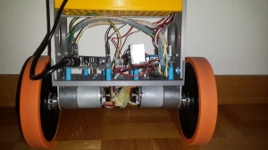
As for the electronics, I use the Raspberry Pi as server for wireless communication and real-time data. The plan in the future is to implement advanced functionalities such as computer vision. The Arduino Mega is taking care of reading sensors and interfacing with the hardware layer. This configuration, I believe allows to make the most of the natural talent of each device and also introduce some complexity in the project to learn how more sophisticated systems would have to be developed. Naturally it is possible to use only Arduino with Bluetooth or WiFi shields, however I think cost-wise there is little advantage in it and you do not benefit from the expansion possibilities. With the solution I present here it will be possible for example to swap the Raspberry Pi with a more performing PC running Linux if more computational power is needed.
The core of the system is the 10 Degree of Freedom Inertial Measurement Unit (10DOF IMU). This piece of hardware only a few year ago would have probably costed thousands, now is available for about 30USD. It consists of a 3 axis accelerometer, magnetometer, gyroscope and 1 barometric pressure sensor plus some magic. Love this little piece of technology.
Motors need to have high RPM and torque. I ude the Pololu 30:1 they have 350 RPM and 110 oz-in so they can guarantee a good momentum and speed to maintain stability. I know of self balancing robots put together without encoders, but I think the little more complexity in the software is compensated by the additional performance, so I recommend to use them. A note on motors that took me some time to understand: they have a dead zone, meaning they usually do not produce enough torque for low PWM values. This has to be considered n the code otherwise the robot will always have a significant delay in the actuation (it looks like the robot hesitates to take action). The solution is re-mapping the PWM value to the minimum desired torque for the motor:
map(speed,0,255,_minimumSpeed,255);
Programming choices and highlights
I am not a programmer so I had to stand on the shoulders of giants and re-use a lot of research available, I hope will be able to do a good job on referencing the sources. Just ask me to add if you see I missed someone. The code I build on was originally from Sebastian Nilsson (see references for link). I think it is a good Idea to look for robot with a similar hardware and design choices and start building from there.
In my final Arduino sketches I decided to use libraries extensively. This has several advantages. First it avoids dealing with low level details not necessarily of interest and second it makes the code more maintainable and easy to share as established libraries are usually also well documented.
Said that, in some cases I started with my own code just to understand the key principles. For example in the initial version I wrote the PID from the scratch. In subsequent versions of the code I switched shared libraries for performances and reliability reasons. Naturally where to draw the line is exquisitely personal: if you feel you want to know everything about say, rotary encoders, feel free to write your own code byte-by-byte.
A notably complex part of the system is the acquisition and fusion of the data from the IMU. Similar to the approach taken for the PID, I initially I coded the reading functions from the scratch part as I think it is a great way to understand the complexity of the core of the robot and then used the excellent FreeSixIMU library. The idea is that each sensor is only very accurate in certain aspect of the measurement. So behind the questions “what is the tilting angle?” there is a lot of sensor filtering, fusing and sampling theory. Specifically, the gyroscope is very good for a few seconds and then readings it start to drift, the accelerometer – on the other hand – is accurate in the short term. On top of that, both sensors are noisy so filtering plays a key role to ensure reliable measures.
It is fascinating how mathematics and software and hardware interact with the external world and how tiny changes in the code have a great repercussion on the robot’s ability to perceive the environment and operate.
The other pivotal element of my design is the remote control, it was also the most difficult part to put together as I just lacked the basic knowledge of the programming environment. I started coding the server to be run on the Raspberry Pi in Python but soon realized that this is not the right language for sockets and real-time data, so I had to re-do everything in Node.io, Socket.io and express.
The great thing about this new re-incarnation of JavaScript is that you can create a web server with a few lines of code and the communication between server and client is event based via sockets. This is useful if you want to give commands to the robot and get feed back telemetry. For example I created HTML page using websockets and gauges from jqchart.com. The server program sends the yaw, pitch and roll information to the remote (the instrument is created as a gauge in a webpage) and when the robot moves the indicators change real time without refreshing the page. Here the few lines to send the info to the client:

setInterval(function(){

socket.emit('status', ArduRead['READ Read_Yaw'], ArduRead['READ Read_Pitch'], ArduRead['READ Read_Roll']);

}, 200);
Remote control and PID tuning
Once all the systems and sub-system have been tested it is time for the another challenge: tuning the PID. Since I implemented two cascading PIDs, I have to adjust 6 parameters, that is the constants for the position and velocity PIDs.
I set these by trial and error, be informed that there are better methods if you are able to model your system mathematically. Control theory is a vast area of engineering and I think it is very well addressed by the links contained in the reference section of this post, look specially at the references of the Wikipedia article, so I will not provide conceptual details here.
As the system is not linear, small variations might means big changes in behavior. I would say tuning the PID is difficult, that’s why I nicknamed the robot “Bailey”, as the earlier versions had drunk behavior (if at all they were able to stand).
I report below my parameters. Two points: a) these are dependent from the design and mostlikley will differ for your robot, b) no guarantee this is the optimal solution, it might just be a local optimum. Nevertheless I hope it will give you an idea of the order of magnitude and a possible starting point.
| Speed PID | Angle PID |
| Kp = 0.4149 Ki = 0.0051 Kd = 0.0060 |
Kp = 8.68 Ki = 4.53 Kd = 0.65 |
Since it is not practical or possible to re-program the Arduino every time you want to try a slightly different settings, you need to have a system to tune the PID parameters real time. I therefore developed the a remote control using node, socket.io and express to create a server. I also implemented in a CSV file generation facility to be able to analyze the data after each robot run.

I designed this remote to be able to adjust the most important settings real time and control the movement of the robot. Some functionalities as the battery or CPU indicators still need to be coded.
My experience in doing this self balancing robot is certainly great and I learnt things that I would not have thought before, including some personal improvement.
Future developments
This is just the beginning. I plan to further develop the platform along three major areas of research:
- Computer vision: it would be great to use the camera to map and navigate the environment. This will allow to create an autonomous robot.
- Optimal control system. The PID works fine but assumes a setpoint to be maintained as input. I would like to have the robot to learn and find the balance point by itself also in case of asymmetrical loads. Such control system should be independent from the geometry of the robot. I am currently exploring options involving Particle Swarn Optimizations that seems promising.
- Improve the communication with the controller, some of the web parts are not refreshed properly.
- Use this experience as basis for more ambitious projects. in particular I am interested in developing a robot that balances on a ball instead of wheels.
References
B. Bonafilia, N. Gustafsson, P. Nyman, S. Nilsson, ‘Self-balancing two-wheeled robot’, 2013. Available from: . [16 September 2014].
R. Chi Ooi, ‘Balancing a Two-Wheeled Autonomous Robot‘, The University of Western Australia
School of Mechanical Engineering, 2003. Available from: . [16 September 2014]. NOTE have a look at the main site and .
M. Gómez, T. Arribas, S. Sánchez, ‘Optimal Control Based on CACM-RL in a Two-Wheeled Inverted Pendulum’, International Journal of Advanced Robotic Systems, 2012, Vol 9, 235:2012.
PID controller. Available from: [16 September 2014]. NOTE: Look carefully at the references of this page.
FreeIMU: an Open Hardware Framework for Orientation and Motion Sensing. Available from: <http://www.varesano.net/projects/hardware/FreeIMU>. [16 September 2014].
OpenSCAD The Programmers Solid 3D CAD Modeller. Available from: . [16 September 2014].
Gauges used in the remote: www.jqchart.com


Pingback: The balancing act of the one-eyed robot #piday #raspberrypi @Raspberry_Pi « adafruit industries blog
Great project! I’m into a project just like yours, in fact i just need to change the wheels by a pair of banebots like yours but in my country nobody sells them, so i have to order them to Banebots or RobotShop, now i’d like to see your Future developments
thanks! you can use the Banebots or 3D print wheels http://www.thingiverse.com/thing:21486. One point with printed wheels is that you need a tire (might be as simple as a rubber band).
Hello,
Nice project and a really good project with a nice ducumentation.
Which motor controllers do you use now?
Best regards
Dani
thanks! The motor driver is based on the L298N chip. Check this for example http://www.ebay.com/itm/L298N-DC-Motor-Driver-Module-Robot-Dual-H-Bridge-Arduino-PIC-AVR-/370877976992?pt=LH_DefaultDomain_0&hash=item565a0cd1a0
Hello Paolo Negrini,
Great project!,I am interest with your projects, I want to learn more about your projects, I have some questions about your projects how to determine configuration.calibratedZeroAngle?
,
Regards,
Gabriel
Hello Gabriel,
thanks for your interest! The configuration.calibratedZeroAngle is determined experimentally. You just have to balance the robot by hand and read the angle from the IMU.
I am now working at an improved version of the robot using stepper motors and upgraded software. As I am not a professional programmer I would welcome any suggestion on the coding.
Ciao,
Paolo
Thanks for the reply
How to put a good imu sensors so that the robot can be balanced well? In your project what angle you take on configuration.calibratedZeroAngle , whether the angle of pitch or roll or yaw ?, and in your project, you are only using the PID tuning method or PID tuning and Kalman filter method?
Thank you Paolo
Regards,
Gabriel